Binary Clock
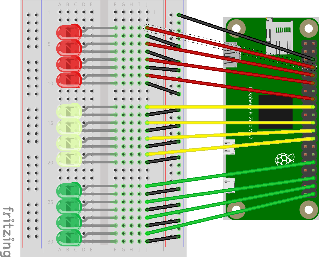
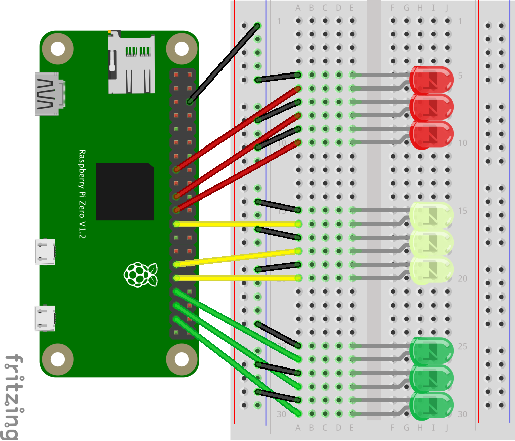
In this lab, you will create the binary clock by continuing to add the seconds, minutes and hours LEDs and then running the clock.py script.
Binary Clock Hardware
Continue pattern started in basic hardware lab.
- Add LED just above the current LED (F28 for - and F27 for +).
- Connect short black wire to negative leg (J28) of LED and negative row.
- Connect long colored wire to positive leg (J27) to GPIO appropriate port according to table below leaving 2 rows between seconds and minutes and another 2 rows between minutes and hours.
| Time | GPIO |
|---|---|
| S1 | 21 |
| S2 | 20 |
| S4 | 16 |
| S8 | 12 |
| S10 | 26 |
| S20 | 19 |
| S40 | 13 |
| M1 | 7 |
| M2 | 8 |
| M4 | 25 |
| M8 | 24 |
| M10 | 6 |
| M20 | 5 |
| M40 | 11 |
| H1 | 23 |
| H2 | 18 |
| H4 | 15 |
| H8 | 14 |
| H10 | 9 |
| H20 | 10 |
| H40 | 22 |


Binary Clock Code
- Change directory to the clock code.
cd binary-clock - Execute clock code (You can find a copy of this in https://github.com/cjudd/binary-clock).
./clock.py - End script with Ctrl+C.
Auto Start Binary Clock Code
Complete the following if you want the clock to auto start when you plug it into power.
- Edit rc.local.
sudo nano /etc/rc.local - Add following before exit 0.
/home/pi/binary-clock/clock.py &