Basic Hardware
During this lab, you will start attaching external hardware such as LEDs and controlling using the Python programming language.

Wire Up LED
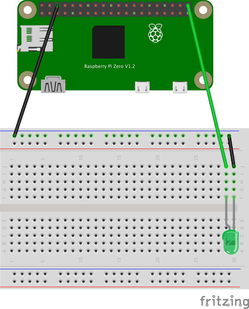
- Add LED (green) to breadboard with netative (shorter) leg in F30 and the positive (longer) leg in F29.
- Add a short black wire connecting J30 to closest negative (-) row.
- Ground the negative row by connecting a long black wire to the top negative (-) row hole around J1 to a Ground on the Raspberry Pi.
- Add a color wire from J29 to GPIO 21.
Controlling LED
- Start interactive Python shell.
python3 - Initialize the LED GPIO.
import RPi.GPIO as GPIO GPIO.setmode(GPIO.BCM) GPIO.setup(21,GPIO.OUT) - Turn LED on.
GPIO.output(21, GPIO.HIGH) - Turn LED off.
GPIO.output(21, GPIO.LOW) - Import time library.
import time - Blink LED.
while True:
 GPIO.output(21, GPIO.HIGH)
 time.sleep(1)
 GPIO.output(21, GPIO.LOW)
 time.sleep(1)
NOTE: The while True creates an infinate loop for all code indentened after it.
- Watch LED blink for a minute or so.
- Ctrl+C to terminate loop.
- Exit Python interactive shell.
exit()
Gpiozero Library
Having to manage the GPIO port can be a hastle in more complicated programs. The Gpiozero Python libary simplifies this.
Documentation: https://gpiozero.readthedocs.io/en/stable/
Controlling LED with Gpiozero
- On the Raspberry Pi command-line, start interactive Python shell.
python3 - Initialize the LED GPIO.
from gpiozero import LED led = LED(21) - Turn LED on.
led.on() - Turn LED off.
led.off() - Blink LED.
led.blink() - Blink LED faster.
led.blink(.1, .1)HINT: https://gpiozero.readthedocs.io/en/stable/api_output.html
- Blink LED slowly 3 times.
led.blink(2, 2, 3) - Exit Python interactive shell.
exit()